|
|
|
|
|
|
|
|
|
|
|
|
 |
|
 |
|
 |
 |
 |
|
|
|
||||||||
|
|
Home | Wall Sawing | About Concrete Foundations | |||||||
|
|
||||||||
|
|
||
|
|
Concrete Doorway Cutting Service 66A Hancock Street Haverhill MA 01832 978-774-6005 info@concrete-foundations.com |
 |
|
|
||
|
|
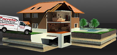
sump pump |
Welcome to Concrete Doorway Cutting ServiceThe spacing for cutting or sawing concrete is determined on a job to job basis. In each case we consider the use of the vertical bonding rods. This consideration may be determined in a somewhat similar manner to the above. At the downward tension on the concrete wall cutting saw caused by the shear from the concrete floor slab on both sides of the saw is equally adjacent even perpendicular to the concrete doorway to be cut.The vertical direction of the concrete wall saw and the stress on the track caused by the hydraulic torque causes diagonal rods of the doorway to appear and should be extended at least 6" into the footing or, if desired, the vertical rods may be hooked around the lower reinforcement.  1) Cutting and Sawing a concrete retaining wall to reduce its height to total at 2 feet height and to carry sand filling which weighs 100 pounds per cubic foot. The wall is also to carry a surcharge due to Cooper's E50 standard hydraulic wall saw loading on each track directed to Plate IV. The weight of the fluid to give the same pressure as that of the filling will be taken at 25 lb. per cubic foot. It will be assumed that the face of the retaining wall is to be sawed into manageable pieces for easy removal. The spacing of the concrete reinforcing rods at other points in the vertical wall may be determined in a similar manner. The arrangement of the pairs of reinforcing rods is shown for Plate III. The locomotives pull directly opposite each other to determine concrete strength and density. It will be assumed that each wall saw track load is distributed laterally over a width equal to the distance between track centers, namely, 10 foot (120 inches.) If we consider a distance of 10 feet in the direction of the wall saw rails, the maximum load on each track may be taken as 100,000 lb. occurring under the locomotive drivers. This load is assumed to act over an area of 10' x 13' =130sf, giving a weight per square foot of concrete forms and ties. This is equivalent to the weight of a Volkswagen and is our only problem, then, is to design a diamond concrete wall saw to sustain a cutting of 800 feet and an 8 ft. surcharge of the same material. The total force acting upon this concrete slab is represented by a fairly dense area of concrete floor. At any given depth the pressure is severe; that is, if it is taken at the total depth, including surcharge. For example, at the top of the concrete footing the pressure per square foot is beyond comprehension and at the top of concrete wall. The pressure at the bottom of the vertical slab is the same as in the preceding design and, since the concrete saw must have the same spacing in both designs, the thickness of slab and spacing of the rods at the bottom may be the same. At a point one-fourth the height of wall above the footing, the required spacing is important to concrete strength and density. Cutting a Concrete Footing.-The total force acting upon the retaining wall is represented by the area 3 and it is clear that (36sq feet) =9000 lb. and acts like a concrete dam. The resultant weight is found to be 34,310 lb. for each lineal foot in length of wall, and acts at a distance 6.14 ft. from the toe. The resultant pressure drawn for the concrete cuts are based exactly at the middle third point. The maximum pressure at the toe is twice this value which is within the allowable. The pressure at the inner extremity of the footing is, of course, is zero. The wall is safe against overturning and sliding, the factors of safety being 2.8 and 1.5 respectively. Cutting Concrete Floor Slab.-We have essentially the same forces acting on the foot strip at the inner extremity as in the preceding cutting. The load on this strip determines the thickness of slab and d = 28 in. will be taken as before, within 6.round holes and the same rod spacing. The uniform load on the end strip is 2550+375 feet pounds. These values are within the allowable for cutting and removing concrete. For each foot strip toward the vertical wall or floor, the unit load is Special Types of Reinforced-concrete walls.- shown is the cellular type of reinforced-concrete retaining wall. This wall is formed of two longitudinal curtain walls (A) and (E), connected by transverse walls (C). The vertical space between the parallel longitudinal walls and the transverse walls is filled with earth. This type of wall gives a lower maximum soil pressure than either the cantilever or concrete core bit types, but under average conditions its cost per linear foot is greater. Its use would seem to be restricted to poor soil with no opportunity to drive piles and where the wall must be built as close as possible to a given 'property line--conditions which often occur in railway work. This shows a design of a wall cutting project which gives a maximum soil pressure even less than the cellular type and which costs approximately the same per linear foot of wall. This design was employed by the Chicago, Milwaukee & St. Paul Ry. in a long retaining wall at Elgin, Ill., and was chosen in preference to the design shown in Fig. 36 on second of the much lower bearing pressure on the soil. Tile wall consists of a footing (Y) which supports a longitudinal wall (1') and the cross walls (U). The cross walls at the outer end support the girder (X), which spans From one concrete cross cut on a wall to another is to be expected. The concrete slabs are supported at one end by the girder and at the other end by the longitudinal wall. The great reduction in soil pressure is brought about mainly by eliminating the weight of the earth directly above the footings, the space between the cross walls being an open and empty space in this design. In this type of wall and in the cellular type as well, stability against sliding should be carefully investigated. Back-filling and Drainage.-Quite as much attention should be paid to the earth filling and to its drainage as to the design and construction of the retaining wall proper or to the matter of providing a suitable concrete foundation. If the earth is deposited in layers inclined from the wall, the pressure will be small compared to that resulting if the layers are sloped toward the wall. It is quite often the case that by depositing the backfilling so as not to slide against the wall, a light wall may be made to stand where, under the same conditions, if the earth is dumped so as to slide against the wall, even a heavy wall will fail. When placing a back-fill near a steep undisturbed slope of earth or rock, care should be taken that the earth does not arch, or does not form a wedge. If the proper precautions are not taken, a heavy lateral thrust will occur near the, top of wall. Water behind a wall is a frequent cause of failure. It adds to the weight of the backing and softens the material so that the lateral thrust is increased. Also, un-drained back filling will freeze and create lateral thrust due to the consequent expansion. To drain the backing, weepers or weep holes should be left through the wall just above the footing. Tile, 3 or 4 in. in diameter is generally used and, in the North Central States, placed usually not more than 10 to 15 ft. apart. The tile should be connected with a longitudinal drain in front of the wall. If the backing is retentive of water, a vertical layer of broken stone, coarse gravel, or cinders should be placed next to the wall to act as a drain. The filling in front of the wall should also be carefully drained. Insulated Concrete Foundations are far superior to conventional concrete forms in every way possible. If you choose any other concrete foundation, then you are just throwing your money away. Remember! An R-50 Insulating Value! Call 978-774-6005 for a Fast, Free Estimate Today We offer Immediate Service Concrete Pouring and Placement in Massachusetts Residential Concrete Foundations Excavating for Concrete Foundations Concrete Footing Installation All Types of Concrete Pouring and Placement We Use Insulated Concrete Forms ( ICF ) to Create the Perfect Foundation for your Dream Home. The Jury's In! ICF's are Better! When it comes to your family's comfort, using less energy and saving the environment there is simply no other choice. Watertown, Wayland, Westford, Weston, Wilmington, Winchester, Woburn, Wellesley, MA, Massachusetts, New Hampshire, Maine, NH, RI, Avon, Bellingham, Braintree, Brookline, Canton, Cohasset, Dedham, Dover, Foxborough, Foxboro, Franklin, Holbrook, Medfield, Medway, Millis, Milton, Needham, Norfolk, Norwood, Plainville, Quincy, Randolph, Sharon, Stoughton, Walpole, Wellesley, Westwood, Weymouth, Wrentham, Massachusetts We are located just north of Boston MA. We provide concrete cutting and core drilling for basement remodeling in the following communities, cities and towns in Massachusetts and more. Immaculate Heart, Camp Kiwanis, Mary Day, Massapoag, Nashoba Ted Wakitatina, Carlisle Station, Cedarwood, Central Square, Centralville, Chelmsford Chestnut Hill, Clematis, Hudson, Kelly Corner, Kendal Green, Kenwood, Kingston, Lake Forest Park, Lakeview, Lexington, Lincoln, Linden, Lindenwood, Littleton Common, Lokerville, Long Pond Park, Lowell, Lower Village, Malden, Maplewood, Marlborough Junction, Maynard, Medford Hillside, Melrose Highlands, Meriams Corner, Metcalf, Middlesex Village, Mishawum, Montrose, Montvale, Morseville, Mount Auburn, Munroe Station, Nabnasse, Natick, Newton Center, Corner Highlands, Lower Falls, Upper Falls, Newtonville, Nine Acre Corner, Nobscot, Nonantum, Norris, North Reading, Nutting Lake, Oak Grove Hill Park, Oaklands, Old City, Paper Mill Village, Parkerville, Pattenville, Pawtucketville, Payson Park, Pepperell, Piety and Pine Lake Rest Massachusetts We are located just north of Boston MA. We provide concrete cutting and core drilling for basement remodeling in the following communities, cities and towns in Massachusetts and more. Pinehurst, Pingryville, Prospectville, Reading Highlands, Rio Vista River Pines, Riverside, Riverview, Robin Hill, Saxonville, Shakerhill, Sherborn, Shirley, Silver Hill, Silver Lake, Somerville, Spring Hill, Stoneham, Stow, Sudbury, Swan, Symmes, Ten Hills, Tewksbury, Junction Thompsonville, Tower Hill, Townsend Harbor, Tyngsboro, Varnumtown, Vose, Waban, American Wakefield, Junction, Walnut, Hill, Waltham, Waltham Highlands, Wamesit, Ward Corner, Watertown, Waverley, Wayland, Wedgemere, Wellington, West Village, Westford, Westford Station, Westlands, Weston Station, Whidden Corner, Whitneys Willowdale, Willows, Wilmington Junction, Winchester Highlands, Winnmere, Winter Hill, Woburn, Accurate Woburn Highlands, Woodland, Woods Corner, Woodville, Workmans Circle and Camp Wyoming in Massachusetts MA |
|